Embedded development, just like any other, often depends on shared code components such as libraries for specific hardware. However, there’s no de-facto industry standard for managing modular projects in this area. We are going to describe one of the ways to do it on a Git repository level. We will mostly concentrate on project organization topics rather than on particular questions of embedded development.
Infrastructure
As an example, we will create a simple program that blinks the LEDs of STM32F4DISCOVERY board by STMicroelectronics. I assume we have a STM32F4DISCOVERY board with ST32F407VGT6 MCU. I’m using Debian 10.6, but for any other OS, the steps are similar. I have ‘stlink-tools’ and ‘gcc-arm-none-eabi’ packages installed. The former is a collection of tools (and ‘st-flash’ in particular) to work with the Discovery board (e.g. ‘st-flash’ writes the compiled binary file to the MCU’s flash using STLink protocol). The latter is a generic ARM cross-compiler as ST32F407VGT6 is ARM Cortex M4 based MCU.
If you don’t have these packages installed do that now:
sudo apt install stlink-tools gcc-arm-none-eabi
STMicroelectronics provides a standard library for ST32F407VGT6 (STSW-STM32065). But instead of using it (not everybody is happy with its APIs), we will develop our own library by using MCU datasheets directly. Another reason to develop our own library is to demonstrate a typical scenario when libraries are developed together with the main project itself and can be reused in other projects.
Although we will have only one project in this post, we will assume there’re other projects reusing the same library. In particular, fixes and updates to the library should get into these projects as well.
We will assume the code to be stored in Git and Atlassian Bitbucket Server/Data Center is used on the server’s side. This is not necessary but would give us a nice UI.
Project Structure
Our project will consist of the following major components:
- main project source file;
- generic library supporting ST32F407VGT6 MCU;
- files and compiler options needed to cross-compile the C code to the ARM platform.
To cross-compile a project, one has to use a number of specific compiler options and also a startup and a linker script file. When having several projects for the same MCU, it makes sense to share these files and options across projects. Thus we will have a common component dedicated to these compilation-related files. We will name this component ‘common’.
We will name the library ‘stm32’ component. The main project will be named ‘embedded-example’.
Step 1. Create the ‘stm32’ project
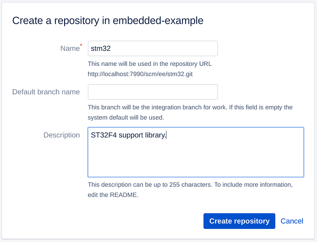
Create ‘stm32’ Git repositrory with Atlassian Bitbucket Server/Data Center UI
and clone it.
git clone http://example.org/scm/ee/stm32.git stm32/
cd stm32/
Create CMakeLists.txt file there:
cmake_minimum_required(VERSION 3.8 FATAL_ERROR)
project(stm32)

add_library(stm32 pin.c gpio.c util.c)
target_include_directories(stm32 PUBLIC .)
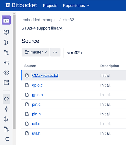
This CMakeLists.txt file describes a project with three C files and tells all the projects that would include it that the include directory is at the project root. So the files structure will be:
├── CMakeLists.txt
├── gpio.c
├── gpio.h
├── pin.c
├── pin.h
├── util.c
└── util.h
Now create these files and their headers.
util.h:
#ifndef __UTIL_H__
#define __UTIL_H__

typedef char hw_boolean_t;

typedef unsigned int uint32_t;
typedef unsigned short uint16_t;
typedef unsigned char uint8_t;

typedef uint32_t hw_address_t;

#ifndef TRUE
#define TRUE 1
#endif

#ifndef FALSE
#define FALSE 0
#endif

#ifndef NULL
#define NULL ((void*)0)
#endif

void hw_apply_bit_change(uint32_t* register_address, int index, uint32_t reset_mask, int bits_per_value, uint32_t mask);
uint32_t hw_get_bit_value(uint32_t* register_address, int index, uint32_t reset_mask, int bits_per_value);

#endif
util.c:
#include "util.h"

void hw_apply_bit_change(uint32_t* register_address, int index, uint32_t reset_mask, int bits_per_value, uint32_t mask) {
  reset_mask = reset_mask << (index * bits_per_value);
  mask = mask << (index * bits_per_value);

  uint32_t value = *register_address;
  value = value & (~reset_mask);
  value = value | mask;
  (*register_address) = value;
}

uint32_t hw_get_bit_value(uint32_t* register_address, int index, uint32_t reset_mask, int bits_per_value) {
  reset_mask = reset_mask << (index * bits_per_value);

  uint32_t value = *register_address;
  value = value & reset_mask;
  value = value >> (index * bits_per_value);
  return value;
}
They contain convenience functions to set and get special bits.
gpio.h:
#ifndef __GPIO_H__
#define __GPIO_H__

#include "pin.h"
#include "util.h"

typedef enum {
  hw_gpio_mode_output_pull_push,
  hw_gpio_mode_output_pull_up,
  hw_gpio_mode_output_pull_down,

  hw_gpio_mode_output_open_drain,
  hw_gpio_mode_output_open_drain_pull_up,
  hw_gpio_mode_output_open_drain_pull_down,

  hw_gpio_mode_alternate_function_pull_push,
  hw_gpio_mode_alternate_function_pull_up,
  hw_gpio_mode_alternate_function_pull_down,

  hw_gpio_mode_alternate_function_open_drain,
  hw_gpio_mode_alternate_function_open_drain_pull_up,
  hw_gpio_mode_alternate_function_open_drain_pull_down,

  hw_gpio_mode_input_floating,
  hw_gpio_mode_input_pull_up,
  hw_gpio_mode_input_pull_down,

  hw_gpio_mode_input_output_analog
} hw_gpio_mode_t;

typedef enum {
  hw_gpio_speed_2mhz,
  hw_gpio_speed_25mhz,
  hw_gpio_speed_50mhz,
  hw_gpio_speed_100mhz
} hw_gpio_speed_t;

typedef enum {
  hw_gpio_alternate_function_none,
  hw_gpio_alternate_function_mco,
  hw_gpio_alternate_function_tamper,
  hw_gpio_alternate_function_swj,
  hw_gpio_alternate_function_trace,
  hw_gpio_alternate_function_rtc_50hz,
  hw_gpio_alternate_function_tim1,
  hw_gpio_alternate_function_tim2,
  hw_gpio_alternate_function_tim3,
  hw_gpio_alternate_function_tim4,
  hw_gpio_alternate_function_tim5,
  hw_gpio_alternate_function_tim8,
  hw_gpio_alternate_function_tim9,
  hw_gpio_alternate_function_tim10,
  hw_gpio_alternate_function_tim11,
  hw_gpio_alternate_function_tim12,
  hw_gpio_alternate_function_tim13,
  hw_gpio_alternate_function_tim14,
  hw_gpio_alternate_function_i2c1,
  hw_gpio_alternate_function_i2c2,
  hw_gpio_alternate_function_i2c3,
  hw_gpio_alternate_function_spi1,
  hw_gpio_alternate_function_spi2,
  hw_gpio_alternate_function_spi3,
  hw_gpio_alternate_function_spi4,
  hw_gpio_alternate_function_spi5,
  hw_gpio_alternate_function_spi6,
  hw_gpio_alternate_function_usart1,
  hw_gpio_alternate_function_usart2,
  hw_gpio_alternate_function_usart3,
  hw_gpio_alternate_function_uart4,
  hw_gpio_alternate_function_uart5,
  hw_gpio_alternate_function_usart6,
  hw_gpio_alternate_function_uart7,
  hw_gpio_alternate_function_uart8,
  hw_gpio_alternate_function_i2s3ext,
  hw_gpio_alternate_function_can1,
  hw_gpio_alternate_function_can2,
  hw_gpio_alternate_function_usb_otg_fs,
  hw_gpio_alternate_function_usb_otg_hs,
  hw_gpio_alternate_function_ethernet,
  hw_gpio_alternate_function_fsmc,
  hw_gpio_alternate_function_usb_otg_hs_fs,
  hw_gpio_alternate_function_sdio,
  hw_gpio_alternate_function_dcmi,
  hw_gpio_alternate_function_eventout,
} hw_gpio_alternate_function_t;

void hw_gpio_configure(hw_pin_t pin, hw_gpio_mode_t mode, hw_gpio_speed_t speed, hw_gpio_alternate_function_t alternate_function);
void hw_gpio_set(hw_pin_t pin, hw_boolean_t on);
hw_boolean_t hw_gpio_get(hw_pin_t pin);

#endif
gpio.c:
#include "gpio.h"

#define PERIPH_BASE 0x40000000
#define AHB1PERIPH_BASE (PERIPH_BASE + 0x00020000)

#define RCC_BASE (AHB1PERIPH_BASE + 0x3800)

#define RCC_CR_OFFSET 0x00
#define RCC_PLL_CFGR_OFFSET 0x04
#define RCC_CFGR_OFFSET 0x08
#define RCC_CIR_OFFSET 0x0C
#define RCC_APB1RSTR_OFFSET 0x20
#define RCC_APB2RSTR_OFFSET 0x24
#define RCC_AHB1ENR_OFFSET 0x30
#define RCC_AHB2ENR_OFFSET 0x34
#define RCC_APB1ENR_OFFSET 0x40
#define RCC_APB2ENR_OFFSET 0x44

#define RCC_CFGR_RESET_VALUE 0x00000000
#define RCC_PLLGCFGR_RESET_VALUE 0x24003010
#define RCC_CIR_RESET_VALUE 0x00000000

#define RCC_CR_HSION_MASK 0x0000000001
#define RCC_CR_HSEON_MASK 0x0000010000
#define RCC_CR_HSERDY_MASK 0x0000020000
#define RCC_CR_HSEBYP_MASK 0x0000040000
#define RCC_CR_CSSON_MASK 0x0000080000
#define RCC_CR_PLLON_MASK 0x1000000
#define RCC_CR_PLLRDY_MASK 0x2000000

#define RCC_APB1ENR_PWREN_MASK 0x10000000

#define APB1PERIPH_BASE       PERIPH_BASE
#define PWR_BASE              (APB1PERIPH_BASE + 0x7000)
#define PWR_CR_OFFSET 0x00

#define PWR_CR_VOS_MASK 0x4000

#define RCC_CFGR_HPRE_MASK 0xF0
#define RCC_CFGR_PPRE1_MASK 0x400
#define RCC_CFGR_PPRE2_MASK 0x2000
#define RCC_CFGR_SW_MASK 0x03
#define RCC_CFGR_SWS_MASK 0x0c

#define RCC_CFGR_PPRE1_DIVIDER4_MASK 0x1400
#define RCC_CFGR_PPRE2_DIVIDER2_MASK 0x8000
#define RCC_CFGR_SW_PLL_MASK 0x02
#define RCC_CFGR_SWS_PLL_MASK 0x08

#define RCC_CFGR_MCO1_MASK 0x600000
#define RCC_CFGR_MCO1_PLL_MASK 0x600000

#define RCC_CFGR_MCO1PRE_MASK 0x7000000
#define RCC_CFGR_MCO1PRE_DIV1_MASK 0x0000000
#define RCC_CFGR_MCO1PRE_DIV2_MASK 0x4000000
#define RCC_CFGR_MCO1PRE_DIV3_MASK 0x5000000
#define RCC_CFGR_MCO1PRE_DIV4_MASK 0x6000000
#define RCC_CFGR_MCO1PRE_DIV5_MASK 0x7000000

#define RCC_CFGR_MCO2_MASK 0xc0000000
#define RCC_CFGR_MCO2_PLL_MASK 0xc0000000

#define RCC_CFGR_MCO2PRE_MASK 0x38000000
#define RCC_CFGR_MCO2PRE_DIV1_MASK 0x00000000
#define RCC_CFGR_MCO2PRE_DIV2_MASK 0x20000000
#define RCC_CFGR_MCO2PRE_DIV3_MASK 0x28000000
#define RCC_CFGR_MCO2PRE_DIV4_MASK 0x30000000
#define RCC_CFGR_MCO2PRE_DIV5_MASK 0x38000000

#define MAX_FREQUENCY 168
#define MAX_PERFORMANCE_PLL_N (MAX_FREQUENCY*2)
#define MAX_PERFORMANCE_PLL_P 2
#define MAX_PERFORMANCE_PLL_Q (MAX_PERFORMANCE_PLL_N / 48)

#define RCC_PLLCFGR_PLLSRC_MASK 0x400000

#define FLASH_ACR_ICEN_MASK 0x100
#define FLASH_ACR_DCEN_MASK 0x200
#define FLASH_LATENCY_5_MASK 0x5

#define FLASH_R_BASE (AHB1PERIPH_BASE + 0x3C00)
#define FLASH_ACR_OFFSET 0x00

#define RCC_APB1ENR_USART2_MASK 0x20000
#define RCC_APB1ENR_USART3_MASK 0x40000
#define RCC_APB1ENR_USART4_MASK 0x80000
#define RCC_APB1ENR_USART5_MASK 0x100000

#define RCC_APB1ENR_I2C1_MASK 0x200000
#define RCC_APB1ENR_I2C2_MASK 0x400000
#define RCC_APB1ENR_I2C3_MASK 0x800000

#define RCC_APB2ENR_USART1_MASK 0x10
#define RCC_APB2ENR_USART6_MASK 0x20
#define RCC_APB2ENR_SYSCFG_MASK 0x4000

#define RCC_AHB2ENR_OTGFS_MASK 0x80
#define RCC_AHB2ENR_DCMI_MASK 0x1

#define RCC_AHB1ENR_DMA1_MASK 0x200000
#define RCC_AHB1ENR_DMA2_MASK 0x400000

#define SYSTICK_FREQUENCY_HZ 100

#define PERIPH_BASE 0x40000000

#define GPIO_BASE (PERIPH_BASE + 0x00020000)

#define GPIO_BYTES_PER_CLASS 0x0400

#define GPIO_MODER_REGISTER_OFFSET 0x00
#define GPIO_OTYPER_REGISTER_OFFSET 0x04
#define GPIO_OSPEEDR_REGISTER_OFFSET 0x08
#define GPIO_PUPDR_REGISTER_OFFSET 0x0c
#define GPIO_IDR_REGISTER_OFFSET 0x10
#define GPIO_ODR_REGISTER_OFFSET 0x14
#define GPIO_BSRR_REGISTER_OFFSET 0x18
#define GPIO_LCKR_REGISTER_OFFSET 0x1c
#define GPIO_AFRL_REGISTER_OFFSET 0x20
#define GPIO_AFRH_REGISTER_OFFSET 0x24

#define GPIO_MODER_RESET_MASK 0x03
#define GPIO_OTYPER_RESET_MASK 0x01
#define GPIO_OSPEEDR_RESET_MASK 0x03
#define GPIO_PUPDR_RESET_MASK 0x03
#define GPIO_ODR_RESET_MASK 0x01
#define GPIO_IDR_RESET_MASK 0x01
#define GPIO_AFRx_RESET_MASK 0x0f

#define GPIO_BITS_PER_MODER_VALUE 2
#define GPIO_BITS_PER_OTYPER_VALUE 1
#define GPIO_BITS_PER_OSPEEDR_VALUE 2
#define GPIO_BITS_PER_PUPDR_VALUE 2
#define GPIO_BITS_PER_ODR_VALUE 1
#define GPIO_BITS_PER_IDR_VALUE 1
#define GPIO_BITS_PER_AFRx_VALUE 4

typedef enum {
  hw_gpio_alternate_function_class_af0 = 0,
  hw_gpio_alternate_function_class_af1,
  hw_gpio_alternate_function_class_af2,
  hw_gpio_alternate_function_class_af3,
  hw_gpio_alternate_function_class_af4,
  hw_gpio_alternate_function_class_af5,
  hw_gpio_alternate_function_class_af6,
  hw_gpio_alternate_function_class_af7,
  hw_gpio_alternate_function_class_af8,
  hw_gpio_alternate_function_class_af9,
  hw_gpio_alternate_function_class_af10,
  hw_gpio_alternate_function_class_af11,
  hw_gpio_alternate_function_class_af12,
  hw_gpio_alternate_function_class_af13,
  hw_gpio_alternate_function_class_af14,
  hw_gpio_alternate_function_class_af15
} hw_gpio_alternate_function_class_t;

hw_gpio_alternate_function_class_t hw_gpio_alternate_function_class_get(hw_gpio_alternate_function_t alternate_function) {
  switch (alternate_function) {
    default:
    case hw_gpio_alternate_function_none:
    case hw_gpio_alternate_function_mco:
    case hw_gpio_alternate_function_tamper:
    case hw_gpio_alternate_function_swj:
    case hw_gpio_alternate_function_trace:
    case hw_gpio_alternate_function_rtc_50hz:
      return hw_gpio_alternate_function_class_af0;
    case hw_gpio_alternate_function_tim1:
    case hw_gpio_alternate_function_tim2:
      return hw_gpio_alternate_function_class_af1;
    case hw_gpio_alternate_function_tim3:
    case hw_gpio_alternate_function_tim4:
    case hw_gpio_alternate_function_tim5:
      return hw_gpio_alternate_function_class_af2;
    case hw_gpio_alternate_function_tim8:
    case hw_gpio_alternate_function_tim9:
    case hw_gpio_alternate_function_tim10:
    case hw_gpio_alternate_function_tim11:
      return hw_gpio_alternate_function_class_af3;
    case hw_gpio_alternate_function_tim12:
    case hw_gpio_alternate_function_tim13:
    case hw_gpio_alternate_function_tim14:
      return hw_gpio_alternate_function_class_af9;
    case hw_gpio_alternate_function_i2c1:
    case hw_gpio_alternate_function_i2c2:
    case hw_gpio_alternate_function_i2c3:
      return hw_gpio_alternate_function_class_af4;
    case hw_gpio_alternate_function_spi1:
    case hw_gpio_alternate_function_spi2:
      return hw_gpio_alternate_function_class_af5;
    case hw_gpio_alternate_function_spi3:
      return hw_gpio_alternate_function_class_af6;
    case hw_gpio_alternate_function_spi4:
    case hw_gpio_alternate_function_spi5:
    case hw_gpio_alternate_function_spi6:
      return hw_gpio_alternate_function_class_af5;
    case hw_gpio_alternate_function_usart1:
    case hw_gpio_alternate_function_usart2:
    case hw_gpio_alternate_function_usart3:
      return hw_gpio_alternate_function_class_af7;
    case hw_gpio_alternate_function_uart4:
    case hw_gpio_alternate_function_uart5:
    case hw_gpio_alternate_function_usart6:
    case hw_gpio_alternate_function_uart7:
    case hw_gpio_alternate_function_uart8:
      return hw_gpio_alternate_function_class_af8;
    case hw_gpio_alternate_function_i2s3ext:
      return hw_gpio_alternate_function_class_af7;
    case hw_gpio_alternate_function_can1:
    case hw_gpio_alternate_function_can2:
      return hw_gpio_alternate_function_class_af9;
    case hw_gpio_alternate_function_usb_otg_fs:
    case hw_gpio_alternate_function_usb_otg_hs:
      return hw_gpio_alternate_function_class_af10;
    case hw_gpio_alternate_function_usb_otg_hs_fs:
      return hw_gpio_alternate_function_class_af12;
    case hw_gpio_alternate_function_ethernet:
      return hw_gpio_alternate_function_class_af11;
    case hw_gpio_alternate_function_fsmc:
    case hw_gpio_alternate_function_sdio:
      return hw_gpio_alternate_function_class_af12;
    case hw_gpio_alternate_function_dcmi:
      return hw_gpio_alternate_function_class_af13;
    case hw_gpio_alternate_function_eventout:
      return hw_gpio_alternate_function_class_af15;
  }
}

void hw_clock_gpio_on(hw_pin_class_t pin_class, hw_boolean_t enable) {
  hw_address_t address = RCC_BASE;
  uint32_t* ahb1enr_register = (uint32_t*)(address + RCC_AHB1ENR_OFFSET);

  hw_apply_bit_change(ahb1enr_register, pin_class, 0x01, 1, enable);
}

void hw_gpio_configure(hw_pin_t pin, hw_gpio_mode_t mode, hw_gpio_speed_t speed, hw_gpio_alternate_function_t alternate_function) {
  hw_pin_class_t pin_class = hw_pin_class_get(pin);
  uint8_t pin_number = hw_pin_number_get(pin);

  hw_address_t address = GPIO_BASE + pin_class * GPIO_BYTES_PER_CLASS;
  uint32_t* moder_register = (uint32_t*)(address + GPIO_MODER_REGISTER_OFFSET);
  uint32_t* otyper_register = (uint32_t*)(address + GPIO_OTYPER_REGISTER_OFFSET);
  uint32_t* ospeedr_register = (uint32_t*)(address + GPIO_OSPEEDR_REGISTER_OFFSET);
  uint32_t* pupdr_register = (uint32_t*)(address + GPIO_PUPDR_REGISTER_OFFSET);
  uint32_t* afrl_register = (uint32_t*)(address + GPIO_AFRL_REGISTER_OFFSET);
  uint32_t* afrh_register = (uint32_t*)(address + GPIO_AFRH_REGISTER_OFFSET);

  hw_clock_gpio_on(pin_class, TRUE);

  uint32_t moder_mask;
  uint32_t otyper_mask;
  hw_boolean_t moder_mask_should_be_applied;
  hw_boolean_t otyper_mask_should_be_applied;
  hw_boolean_t ospeed_mask_should_be_applied;
  switch (mode) {
    case hw_gpio_mode_output_pull_push:
    case hw_gpio_mode_output_pull_up:
    case hw_gpio_mode_output_pull_down:
      otyper_mask = 0x00;
      moder_mask = 0x01;
      otyper_mask_should_be_applied = TRUE;
      moder_mask_should_be_applied = TRUE;
      ospeed_mask_should_be_applied = TRUE;
      break;
    case hw_gpio_mode_output_open_drain:
    case hw_gpio_mode_output_open_drain_pull_up:
    case hw_gpio_mode_output_open_drain_pull_down:
      otyper_mask = 0x01;
      moder_mask = 0x01;
      otyper_mask_should_be_applied = TRUE;
      moder_mask_should_be_applied = TRUE;
      ospeed_mask_should_be_applied = TRUE;
      break;
    case hw_gpio_mode_alternate_function_pull_push:
    case hw_gpio_mode_alternate_function_pull_up:
    case hw_gpio_mode_alternate_function_pull_down:
      otyper_mask = 0x00;
      moder_mask = 0x02;
      otyper_mask_should_be_applied = TRUE;
      moder_mask_should_be_applied = TRUE;
      ospeed_mask_should_be_applied = TRUE;
      break;
    case hw_gpio_mode_alternate_function_open_drain:
    case hw_gpio_mode_alternate_function_open_drain_pull_up:
    case hw_gpio_mode_alternate_function_open_drain_pull_down:
      otyper_mask = 0x01;
      moder_mask = 0x02;
      otyper_mask_should_be_applied = TRUE;
      moder_mask_should_be_applied = TRUE;
      ospeed_mask_should_be_applied = TRUE;
      break;
    case hw_gpio_mode_input_floating:
    case hw_gpio_mode_input_pull_up:
    case hw_gpio_mode_input_pull_down:
      moder_mask = 0x00;
      otyper_mask_should_be_applied = FALSE;
      moder_mask_should_be_applied = TRUE;
      ospeed_mask_should_be_applied = FALSE;
      break;
    case hw_gpio_mode_input_output_analog:
      otyper_mask_should_be_applied = FALSE;
      moder_mask_should_be_applied = TRUE;
      ospeed_mask_should_be_applied = FALSE;
      moder_mask = 0x03;
      break;
    default:
      moder_mask_should_be_applied = FALSE;
      otyper_mask_should_be_applied = FALSE;
      ospeed_mask_should_be_applied = FALSE;
      break;
  }
  uint32_t ospeedr_mask;
  switch (speed) {
    default:
    case hw_gpio_speed_2mhz:
      ospeedr_mask = 0x00;
      break;
    case hw_gpio_speed_25mhz:
      ospeedr_mask = 0x01;
      break;
    case hw_gpio_speed_50mhz:
      ospeedr_mask = 0x02;
      break;
    case hw_gpio_speed_100mhz:
      ospeedr_mask = 0x03;
      break;
  }
  uint32_t pupdr_mask;
  hw_boolean_t pupdr_mask_should_be_applied;
  switch (mode) {
    case hw_gpio_mode_output_pull_push:
    case hw_gpio_mode_output_open_drain:
    case hw_gpio_mode_alternate_function_pull_push:
    case hw_gpio_mode_alternate_function_open_drain:
    case hw_gpio_mode_input_floating:
    case hw_gpio_mode_input_output_analog:
      pupdr_mask = 0x00;
      pupdr_mask_should_be_applied = TRUE;
      break;

    case hw_gpio_mode_output_pull_up:
    case hw_gpio_mode_output_open_drain_pull_up:
    case hw_gpio_mode_alternate_function_pull_up:
    case hw_gpio_mode_alternate_function_open_drain_pull_up:
    case hw_gpio_mode_input_pull_up:
      pupdr_mask = 0x01;
      pupdr_mask_should_be_applied = TRUE;
      break;

    case hw_gpio_mode_output_pull_down:
    case hw_gpio_mode_output_open_drain_pull_down:
    case hw_gpio_mode_alternate_function_pull_down:
    case hw_gpio_mode_alternate_function_open_drain_pull_down:
    case hw_gpio_mode_input_pull_down:
      pupdr_mask = 0x02;
      pupdr_mask_should_be_applied = TRUE;
      break;
    default:
      pupdr_mask_should_be_applied = FALSE;
      break;
  }
  if (moder_mask_should_be_applied) {
    hw_apply_bit_change(moder_register, pin_number, GPIO_MODER_RESET_MASK, GPIO_BITS_PER_MODER_VALUE, moder_mask);
  }
  if (otyper_mask_should_be_applied) {
    hw_apply_bit_change(otyper_register, pin_number, GPIO_OTYPER_RESET_MASK, GPIO_BITS_PER_OTYPER_VALUE, otyper_mask);
  }
  if (ospeed_mask_should_be_applied) {
    hw_apply_bit_change(ospeedr_register, pin_number, GPIO_OSPEEDR_RESET_MASK, GPIO_BITS_PER_OSPEEDR_VALUE, ospeedr_mask);
  }
  if (pupdr_mask_should_be_applied) {
    hw_apply_bit_change(pupdr_register, pin_number, GPIO_PUPDR_RESET_MASK, GPIO_BITS_PER_PUPDR_VALUE, pupdr_mask);
  }

  if (alternate_function != hw_gpio_alternate_function_none) {
    uint32_t* af_register = (pin_number < (PINS_PER_CLASS / 2)) ? afrl_register : afrh_register;
    int index = (pin_number < (PINS_PER_CLASS / 2)) ? pin_number : pin_number - (PINS_PER_CLASS / 2);
    hw_gpio_alternate_function_class_t alternate_function_class = hw_gpio_alternate_function_class_get(alternate_function);
    hw_apply_bit_change(af_register, index, GPIO_AFRx_RESET_MASK, GPIO_BITS_PER_AFRx_VALUE, alternate_function_class);
  }
}

void hw_gpio_set(hw_pin_t pin, hw_boolean_t on) {
  hw_pin_class_t pin_class = hw_pin_class_get(pin);
  uint8_t pin_number = hw_pin_number_get(pin);

  hw_address_t address = GPIO_BASE + pin_class * GPIO_BYTES_PER_CLASS;
  uint32_t* odr_register = (uint32_t*)(address + GPIO_ODR_REGISTER_OFFSET);

  on = on & 0x01;
  hw_apply_bit_change(odr_register, pin_number, GPIO_ODR_RESET_MASK, GPIO_BITS_PER_ODR_VALUE, on);
}

hw_boolean_t hw_gpio_get(hw_pin_t pin) {
  hw_pin_class_t pin_class = hw_pin_class_get(pin);
  uint8_t pin_number = hw_pin_number_get(pin);

  hw_address_t address = GPIO_BASE + pin_class * GPIO_BYTES_PER_CLASS;
  uint32_t* idr_register = (uint32_t*)(address + GPIO_IDR_REGISTER_OFFSET);

  return hw_get_bit_value(idr_register, pin_number, GPIO_IDR_RESET_MASK, GPIO_BITS_PER_IDR_VALUE);
}
I will not give any comments tp gpio.c and gpio.h, they contain a dull and straightforward implementation of ST32F407VGT6 datasheet GPIO specifications.
Finally, pin.h:
#ifndef __PIN_H__
#define __PIN_H__

#define PINS_PER_CLASS 16

typedef enum {
  hw_pin_unknown = -1,
  hw_pin_PA0 = 0,
  hw_pin_PA1,
  hw_pin_PA2,
  hw_pin_PA3,
  hw_pin_PA4,
  hw_pin_PA5,
  hw_pin_PA6,
  hw_pin_PA7,
  hw_pin_PA8,
  hw_pin_PA9,
  hw_pin_PA10,
  hw_pin_PA11,
  hw_pin_PA12,
  hw_pin_PA13,
  hw_pin_PA14,
  hw_pin_PA15,
  hw_pin_PB0 = PINS_PER_CLASS,
  hw_pin_PB1,
  hw_pin_PB2,
  hw_pin_PB3,
  hw_pin_PB4,
  hw_pin_PB5,
  hw_pin_PB6,
  hw_pin_PB7,
  hw_pin_PB8,
  hw_pin_PB9,
  hw_pin_PB10,
  hw_pin_PB11,
  hw_pin_PB12,
  hw_pin_PB13,
  hw_pin_PB14,
  hw_pin_PB15,
  hw_pin_PC0 = (PINS_PER_CLASS*2),
  hw_pin_PC1,
  hw_pin_PC2,
  hw_pin_PC3,
  hw_pin_PC4,
  hw_pin_PC5,
  hw_pin_PC6,
  hw_pin_PC7,
  hw_pin_PC8,
  hw_pin_PC9,
  hw_pin_PC10,
  hw_pin_PC11,
  hw_pin_PC12,
  hw_pin_PC13,
  hw_pin_PC14,
  hw_pin_PC15,
  hw_pin_PD0 = (PINS_PER_CLASS*3),
  hw_pin_PD1,
  hw_pin_PD2,
  hw_pin_PD3,
  hw_pin_PD4,
  hw_pin_PD5,
  hw_pin_PD6,
  hw_pin_PD7,
  hw_pin_PD8,
  hw_pin_PD9,
  hw_pin_PD10,
  hw_pin_PD11,
  hw_pin_PD12,
  hw_pin_PD13,
  hw_pin_PD14,
  hw_pin_PD15,
  hw_pin_PE0 = (PINS_PER_CLASS*4),
  hw_pin_PE1,
  hw_pin_PE2,
  hw_pin_PE3,
  hw_pin_PE4,
  hw_pin_PE5,
  hw_pin_PE6,
  hw_pin_PE7,
  hw_pin_PE8,
  hw_pin_PE9,
  hw_pin_PE10,
  hw_pin_PE11,
  hw_pin_PE12,
  hw_pin_PE13,
  hw_pin_PE14,
  hw_pin_PE15
} hw_pin_t;

typedef enum {
  hw_pin_PA = 0,
  hw_pin_PB = 1,
  hw_pin_PC = 2,
  hw_pin_PD = 3,
  hw_pin_PE = 4
} hw_pin_class_t;

#define hw_pin_led_green hw_pin_PD12
#define hw_pin_led_orange hw_pin_PD13
#define hw_pin_led_red hw_pin_PD14
#define hw_pin_led_blue hw_pin_PD15
#define hw_pin_user_button hw_pin_PA0

hw_pin_class_t hw_pin_class_get(hw_pin_t pin);
char hw_pin_number_get(hw_pin_t pin);

#endif
and pin.c:
#include "pin.h"

hw_pin_class_t hw_pin_class_get(hw_pin_t pin) {
  return pin / PINS_PER_CLASS;
}

char hw_pin_number_get(hw_pin_t pin) {
  return pin % PINS_PER_CLASS;
}
As the file names imply, they just define pin names like hw_pin_PD12 and their convenience equivalents like hw_pin_led_green. For instance, on STM32F4DISCOVERY PD12 pin of the MCU is connected to the green LED, that’s why it’s convenient to define:
#define hw_pin_led_green hw_pin_PD12
Now add, commit, and push the changes to ‘stm32’ library:
git add *.c
git add *.h
git add CMakeLists.txt
git commit -m "Initial."
git push origin master
I would note that as this library is self-contained, one can even compile (but not cross-compile, so far) it:
mkdir build
cd build
cmake ..
make
If everything compiles, it’s a good indicator, though a pretty useless property as our target platform is ARM.
Step 2. Create the ‘common’ project
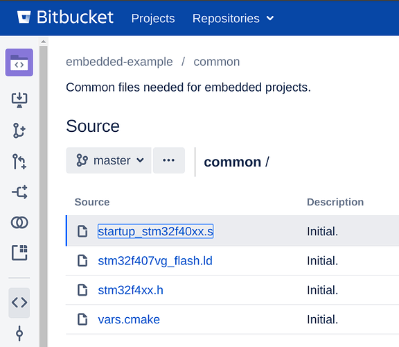
This project will contain the common configuration that is shared between projects. It’s also convenient to put it into a separate Git repository and insert it into each project repository to be included by the project CMakeLists.txt.
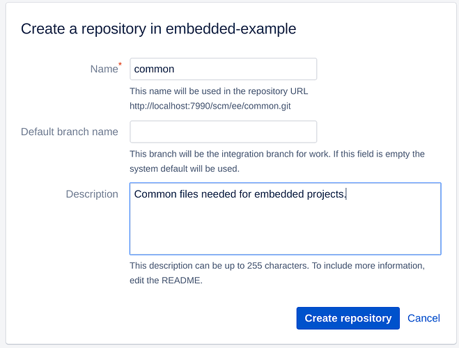
Create the ‘common’ repository with Atlassian Bitbucket Server/Data Center
and clone the newly created repository:
git clone http://example.org/scm/ee/common.git common/
cd common/
Now create vars.cmake:
set(CMAKE_SYSTEM_NAME      Generic)
set(CMAKE_SYSTEM_VERSION   1)
set(CMAKE_SYSTEM_PROCESSOR arm-eabi)

set(CMAKE_C_COMPILER       arm-none-eabi-gcc)
set(CMAKE_CXX_COMPILER     arm-none-eabi-g++)
set(CMAKE_ASM_COMPILER     arm-none-eabi-as)
set(CMAKE_OBJCOPY          arm-none-eabi-objcopy)
set(CMAKE_OBJDUMP          arm-none-eabi-objdump)

set(CMAKE_C_FLAGS "-mthumb -mcpu=cortex-m4 -fno-builtin -Wall -Wno-pointer-to-int-cast -std=gnu99 -fdata-sections -ffunction-sections" CACHE INTERNAL "c compiler flags")
set(CMAKE_CXX_FLAGS "-mthumb -mcpu=cortex-m4 -fno-builtin -Wall -Wno-pointer-to-int-cast -fdata-sections -ffunction-sections" CACHE INTERNAL "cxx compiler flags")
set(CMAKE_ASM_FLAGS "-mthumb -mcpu=cortex-m4" CACHE INTERNAL "asm compiler flags")

set(CMAKE_EXE_LINKER_FLAGS "-nostartfiles -Wl,--gc-sections -mthumb -mcpu=cortex-m4" CACHE INTERNAL "exe link flags")
set(CMAKE_SHARED_LIBRARY_LINK_C_FLAGS CACHE INTERNAL "reset default flags")

set(STM32_STLINK_CLI_EXECUTABLE "st-flash")
This file defines various variables needed for the cross-compilation of sources with ARM as the target platform. It sets compiler flags and a path to the ‘st-flash’ utility that writes binary files to MCU.
Also add stm32f407vg_flash.ld, startup_stm32f40xx.s, and stm32f4xx.h files. I will not cite them here, but they are quite standard and distributed by STMicroelectronics.
So the repository content becomes:
├── startup_stm32f40xx.s
├── stm32f407vg_flash.ld
├── stm32f4xx.h
└── vars.cmake
Commit and push the changes:
git add vars.cmake stm32f4xx.h startup_stm32f40xx.s stm32f407vg_flash.ld
git commit -m "Initial."
git push origin master
Step 3. The project repository
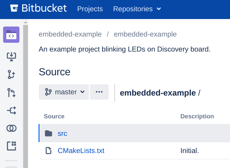
Now let’s create the main project repository. The repository will have the following structure:
├── CMakeLists.txt
├── common   <--- here common.git will be inserted
├── libs
│   └── stm32  <--- here stm32.git will be inserted
│
└── src
    └── main.c
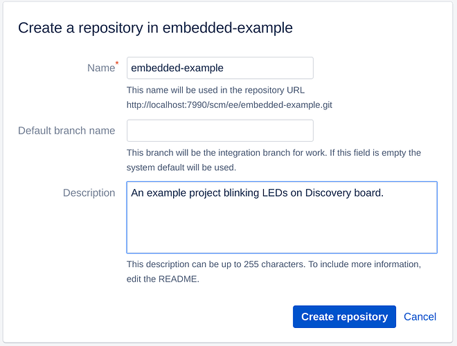
So create an empty Git repository using Atlassian Bitbucket Server/Data Center UI
and clone it:
git clone http://example.org/scm/ee/embedded-example.git embedded-example/
cd embedded-example/
Create CMakeLists.txt there:
cmake_minimum_required(VERSION 3.8 FATAL_ERROR)
include(common/vars.cmake)
project(embedded-example)
enable_language(C ASM)

add_subdirectory(libs/stm32)

set(CMAKE_EXE_LINKER_FLAGS "${CMAKE_EXE_LINKER_FLAGS} -T${CMAKE_SOURCE_DIR}/common/stm32f407vg_flash.ld")

add_executable(${PROJECT_NAME}.elf
    ${CMAKE_SOURCE_DIR}/common/startup_stm32f40xx.s
    ${CMAKE_SOURCE_DIR}/src/main.c)
target_include_directories(${PROJECT_NAME}.elf PRIVATE stm32)
target_link_libraries(${PROJECT_NAME}.elf PRIVATE stm32)

add_custom_target(${PROJECT_NAME}.hex DEPENDS ${PROJECT_NAME}.elf COMMAND ${CMAKE_OBJCOPY} -Oihex ${PROJECT_NAME}.elf ${PROJECT_NAME}.hex)
add_custom_target(${PROJECT_NAME}.bin DEPENDS ${PROJECT_NAME}.elf COMMAND ${CMAKE_OBJCOPY} -Obinary ${PROJECT_NAME}.elf ${PROJECT_NAME}.bin)
set(STLINK_CMD ${STM32_STLINK_CLI_EXECUTABLE} write ${CMAKE_BINARY_DIR}/${PROJECT_NAME}.bin 0x8000000)
add_custom_target(write-flash DEPENDS ${PROJECT_NAME}.bin COMMAND ${STLINK_CMD})
It’s important to call include() on the file with common variables before project() call otherwise CMake falls into an infinite loop (I would consider this strange behavior as a CMake bug). It’s also important to specify the linker script that we’ve put into the ‘common.git’ project.
add_subdirectory() call includes the library. We can include several libraries there. The libraries will be inserted in the libs/ directory.
The last line creates a make write-flash target that will not only create a binary file for the MCU but also will write it into its flash using STLink protocol. ${STM32_STLINK_CLI_EXECUTABLE} is defined in the ‘common’ project.
Now create src/main.c file:
#include <gpio.h>

hw_pin_t leds[] = {
  hw_pin_led_red,
  hw_pin_led_green,
  hw_pin_led_blue,
//  hw_pin_led_orange
};

int leds_count = sizeof(leds) / sizeof(hw_pin_t);

void SystemInit() {
}

int main() {
  hw_gpio_configure(hw_pin_led_blue, hw_gpio_mode_output_pull_push, hw_gpio_speed_2mhz, hw_gpio_alternate_function_none);
  hw_gpio_configure(hw_pin_led_green, hw_gpio_mode_output_pull_push, hw_gpio_speed_2mhz, hw_gpio_alternate_function_none);
  hw_gpio_configure(hw_pin_led_orange, hw_gpio_mode_output_pull_push, hw_gpio_speed_2mhz, hw_gpio_alternate_function_none);
  hw_gpio_configure(hw_pin_led_red, hw_gpio_mode_output_pull_push, hw_gpio_speed_2mhz, hw_gpio_alternate_function_none);

  int current_led = 0;

  while (TRUE) {
    hw_gpio_set(leds[current_led], FALSE);
    current_led = (current_led + 1) % leds_count;
    hw_gpio_set(leds[current_led], TRUE);

    int delay = 1000000;
    while (delay--) {
    }
  }
}
This file is simple: it initializes pins related to LEDs and blinks with red, green, and blue pins. We’ve commented out the orange pin as default STM32F4DISCOVERY firmware blinks with all 4 LEDs and we want to differ from that.
Commit and push the changes:
git add src/main.c
git add CMakeLists.txt
git commit -m "Initial."
git push origin master
Step 4. Insert ‘common.git’ and ‘stm32.git’ repositories into ‘embedded-example.git’
To insert one repository to another we will use Git X-Modules. For Atlassian Bitbucket Server/Data Center there’s a dedicated app with a nice UI. For other Git servers use the: Git X-Modules Command-Line Tool.
Make sure you have X-Modules app installed into Atlassian Bitbucket Server/Data Center. If not, visit Administration | Find new apps | Search the [Marketplace](https://marketplace.atlassian.com/apps/1223696/git-x-modules-for-bitbucket-server) and type “X-Modules” from Bitbucket Server/Data Center UI.
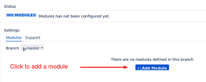
Go to the ‘embedded-example’ Git repository page. When the Git X-Modules app is installed there’s a Git X-Modules button on the left panel, click it.
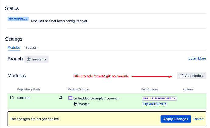
Then click ‘Add Module’ to add the first module (let it be ‘common.git’).
Choose ‘common’ repository and ‘master’ branch. Make sure “This Repository Path:” is ‘common’. It’s the path where the repository will be inserted:
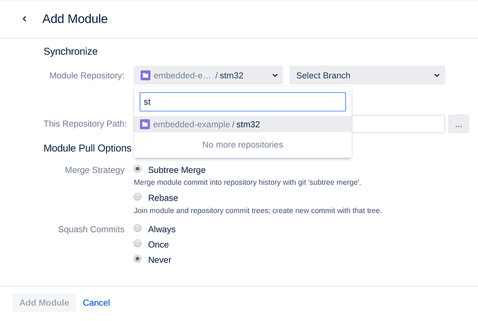
Click ‘Add Module’. Without applying the changes click ‘Add Module’ again to add ‘stm32’ repository as module.
Choose ‘stm32’ repository and ‘master’ branch.
Make sure “This Repository Path:” is “libs/stm32”, this is the insertion path for ‘stm32.git’ repository.
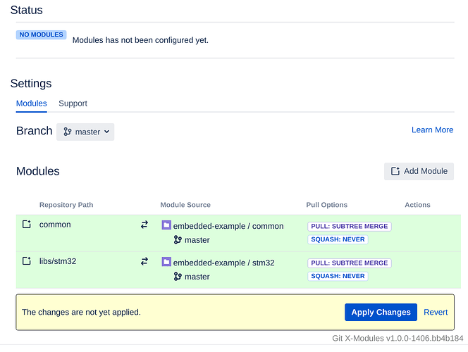
Click ‘Add Module’ and apply the changes.
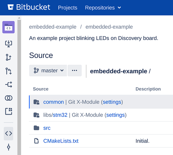
Now the repositories are inserted as X-Modules.
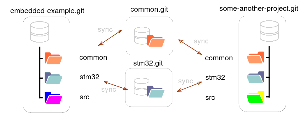
This means that ‘common.git’ and ‘stm32.git’ are synchronized with corresponding directories (‘common’ and ‘libs/stm32’ respectively) of ‘embedded-example.git’.
Fetch the changes from ‘embedded-example’:
cd embedded-example/
git pull --rebase
Now the project contains everything:
├── CMakeLists.txt
├── common
│   ├── startup_stm32f40xx.s
│   ├── stm32f407vg_flash.ld
│   ├── stm32f4xx.h
│   └── vars.cmake
├── libs
│   └── stm32
│       ├── CMakeLists.txt
│       ├── gpio.c
│       ├── gpio.h
│       ├── pin.c
│       ├── pin.h
│       ├── util.c
│       └── util.h
└── src
    └── main.c
Check that the project compiles:
mkdir build
cd build
cmake ..
make
make write-flash

At the moment of running make write-flash, the STM32F4DISCOVERY board should be connected. If you do everything correctly, you’ll see 3 LEDs blinking.
This repository structure can be reused for any other ST32F407VGT6-based project, it’s enough to insert ‘common’ and ‘stm32’ at the corresponding places. Moreover, the directories are bi-directionally synchronized with the inserted repositories, so one can change, see the results, and modify ‘stm32’ directly from the project repository.
